Nodes
Loki3D is a node-based visual programming language. Everything in Loki3D is a node, and interesting things happen when you connect those nodes together.
There are various types of nodes. Some nodes create geometry that can be rendered. Some nodes modify that geometry, or move it to a new place. Some nodes create images or manipulate images for image processing. Some nodes create or manipulate audio, or particles, or shaders, or interactive behaviors.
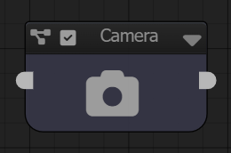
Graphs
A collection of nodes and their connections is a Graph. All Loki3D scenes are graphs. A graph can also contain sub-graphs, or references to other scene graphs.

Creating Nodes
Nodes are created in the Graph Panel.
To create a node, Right-Click or Long-Press in the Graph Panel.
You can also press the Tab key while the mouse is on the Graph Panel. This presents
the Node Creation menu.
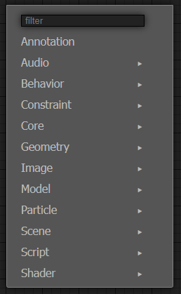
You can type into the Filter field to find a specific node.
Node Data
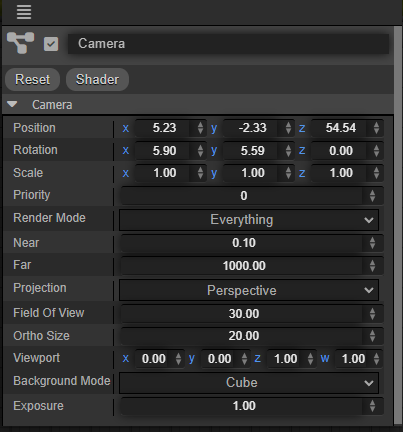
A node is essentially a function that generates data. It has inputs, called properties, and outputs, which are generated by the node's compute function. For example, an "add operator" node would have two inputs, and a compute function to add those two inputs values together to set the node's output. If you select a node, an Inspector panel will be presented to let you edit the properties of the node.
Node Sockets
Node inputs and outputs have sockets, which allow nodes to be connected to each other. An output of one node can be connected to an input of another node, if they are of compatible data types. When a node gets an inputs current value, if the input has a connection to another node, that node will compute the value for the input.
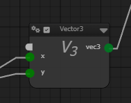
Only inputs and outputs of compatible data types can be connected to each other. For example, a node may compute a vec2 output, and that can only be connected to a vec2 input. An input may declare it can accept multiple types, such as a vec3, vec4, or image connections. In this case, the node changes its behavior based on the type of input, such as using an image texture instead of a solid color. An input or output can also declare it's type as dynamic. In this case, an input can accept any type, and a dynamic output will determine its actual type based on the node's inputs. For example, a math operator node can accept any inputs, and it's output type is determined by the types of its inputs.
Compact Sockets
To keep the size of the node smaller, a node will only display connected sockets. Non-connected sockets are accessible from Compact Sockets. These sockets are white, at the top of the node. Input compact socket is on the left side of the node, and the output compact socket is on the right side of the node.
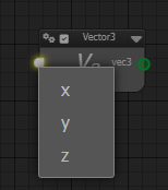
If you click on a Compact Socket, it will present a menu with the available sockets to connect to or from. If you drop a connection link onto a compact socket, or onto the node itself, it will present a menu to choose the socket to connect to or from.
Compact Sockets will not be presented if there is only one input or output for the node, or if all inputs or outputs are connected.
Socket Connections
An output socket of a node can be connected to an input socket of another node. Click on an output socket, select the output to connect from. Then click on an input socket of another node.
You can drop a connection linke onto the node itself instead of the compact socket. If there is only one possible socket that can be connected to, it will automatically be connected to that socket without presenting the socket selection menu.
You can also right-click (or long-touch) on a node and select Connect Input or Connect Output from the context menu.
Disconnecting Socket Connections
To disconnect a connection to an input socket, drag from the socket from the connection and drop onto the graph background.
You can also right-click (or long-touch) on a node and select Disconnect Input or Disconnect Output from the context menu.
Node Enabled State
Nodes have an enabled state, presented as a check-box on the top-left corner of the node. A node will only be computed if it is enabled.
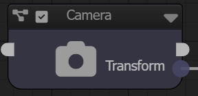
If you click on the enabled state checkbox of node, it will cycle it through the different enabled states for the node.
Pass-Through State

A node in pass-through state will not be computed, but will instead return the data from the first compatible input socket. This lets you disable the node without having to remove it from the graph.
Disabled State

A node in disabled state will not be computed and will return no data.
Node Computation
A node will be computed if an output socket is queried, and that output socket is considered "dirty", meaning its data is no longer valid. Changing the value of a node's input will dirty its output sockets. If an output socket is queried and its data is dirt, it will call on the node to compute new data for the output socket.
For example, a Sphere geometry node generates sphere mesh geometry data for its output geometry socket. When the frame is rendered for the first frame, the sphere node's output socket does not yet have data, so it will have the node compute new data for it, generating the sphere mesh. That sphere mesh geometry is then stored with the output socket, and used to render a sphere. For the next frame, the sphere's output socket is queried, it already has valid mesh data, and the node will not need to be re-computed. However, if you change a property of the sphere node, such as the sphere's radius, it will dirty the output socket and the next time the node's output is queried, it will need to be recomputed.
In the Graph Panel, you can highlight computing nodes to see what nodes are being computed over time.
Renderable Nodes
Some nodes are special and directly contribute to the image on the screen. All scenes need at least one Camera scene node to render anything. A camera node finds all of the objects and geometry in the scene and renders them to the screen, along with any lights it finds. Without a Camera node, nothing wil be rendered.
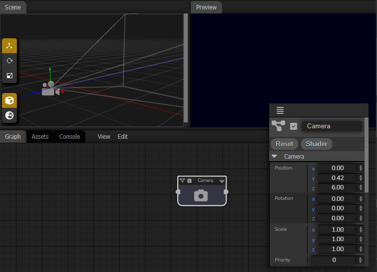
A camera will look for all Scene Object nodes for geometry to render. An Object node provides a Transformation, and Geometry and optional Material to render the geometry with. The camera will a also find any Geometry nodes that do not have an output connection. These provide geometry, but do not have a Transform. The ability to render Geometry nodes without them being connected to an Object node is a convenience feature, reducing the number of nodes needed when you don't need to transform the geometry.
Node Types
There are different types of nodes in Loki3D, but essentially they are functions that generate data, or modify incoming data in some way. One node may generate the geometry of a sphere, and another node may modify that geometry by displacing the points. A node may provide an image from a frame of video, and another node may modify that image by applying an effect to it.
Fundamentally, all of the different node types are all the same, they all have inputs, outputs, and compute the data for their outputs. The categorization of the different types is more for the convenience of identifying their basic behavior, and the different node types have helper functions to assist in how they compute their particular type of data.
There are different types of node categories:
Scene Nodes
Scene nodes define the scene graph to be rendered, including Cameras, Lights, and Objects.
Without a Camera, nothing will be drawn.
Core Nodes
Core nodes provide miscelaneous functions.
Geometry Nodes
Geometry nodes create and modify geometry, which can be rendered by Object scene nodes.
Particle Nodes
Particle nodes create and modify the behavior of particle systems.
Image Nodes
Image nodes create and modify images.
Image nodes are also used to create post render filter effects.
Shader Nodes
Shader nodes create materials used to render geometry by Object scene nodes.
Audio Nodes
Audio nodes create, filter and play sound.
Behavior Nodes
Respond to real-time events, allowing for user interactions and dynmamic behaviors.
Constraint Nodes
Constraint nodes are used to modify transformations of objects. They can be used to aim one
object to another, for example.
