Graph Panel
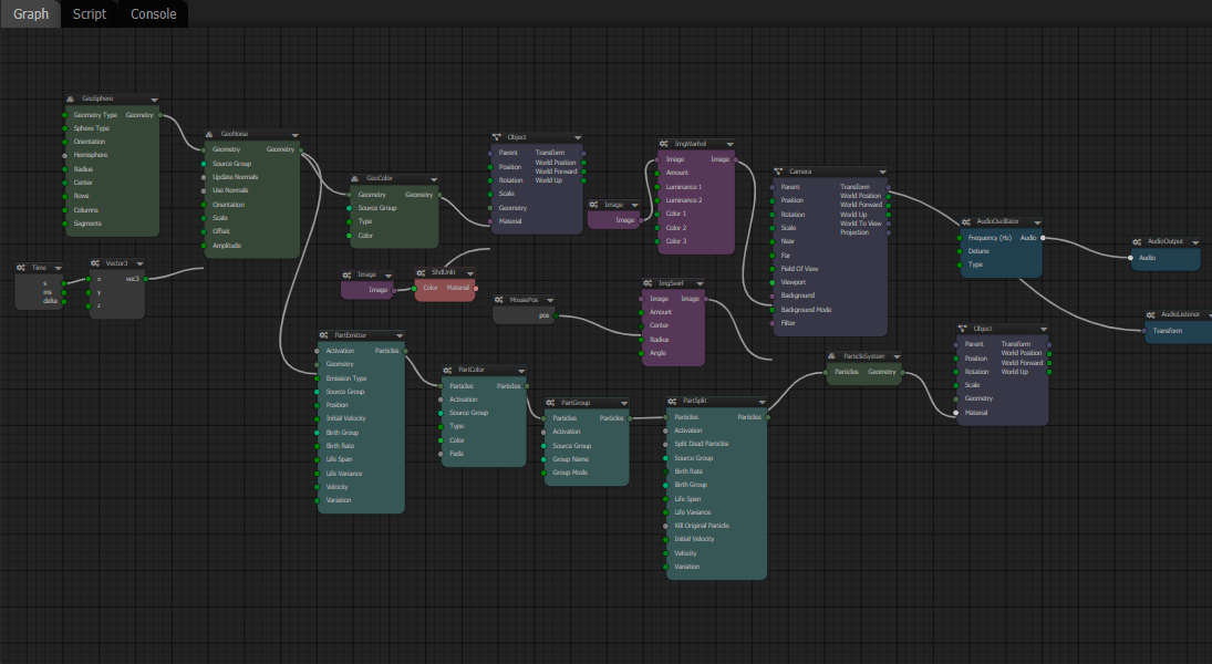
Being a node-based procedural content editor, the Graph Panel is the primary work area of Loki3D. It is where you create and connect nodes for your Loki3D scene.

View Navigation
Mouse
- LMB drag from the graph background to pan the view.
- Alt+LMB drag from anywhere on the graph to pan the view.
- Scroll Wheel to zoom the view in or out.
- Alt+RMB drag up/down to zoom the view in or out.
Touch
- One Finger drag from the graph background (not a node) to pan the view.
- Two Finger drag from anywhere on the graph to pan the view.
- Two Finger pinch to zoom the view in or out.
Keyboard
- + key to zoom the view in.
- - key to zoom the view out.
- A key to frame all nodes.
- F key to frame selected nodes.
Selecting Nodes
Mouse: LMB click on a node to select it.
Touch: Tap a node to select it.
Rectangle Selection
- Ctrl+LMB to rectangle select multiple nodes.
Creating Nodes
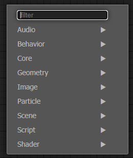
Mouse: RMB click on the graph background to present node creation menu.
Touch: Long Press on the graph to present the node creation menu.
Keyboard: Press the Tab key while the mouse is over the graph for the creation menu.

You can navigate the menu to find the node you're looking for. The menus are organized by node type at the top level of the menu, so Geometry related nodes are under the Geometry sub-menu. You can type into the Filter field of the menu to find specific nodes.
Deleting Nodes
Select the nodes you wish to delete, then:Keyboard: Press the Delete key to delete the selected nodes.
Mouse: RMB click on a node and select Delete Node from the context menu.
Touch: Long Press on a node and select Delete Node from the context menu.
Menu: Select Graph / Delete Selected Nodes from the Graph Panel menu.
Moving Nodes
Mouse: LMB drag a node to move it, and other selected nodes.
Touch: Single Finger drag a node to move the node.
Connecting Nodes
In Loki3D, nodes have input and output connectors, which can be connected together with links.- Only an output connector can be connected to an input connector.
- An input connector can only have a single link to it, while an output connector can be linked to many inputs.
- An output connector cam only be connected to an input connector if they are of compatible data types.
- The color of a connector gives a hint about its data type. In general, like-colors can be connected together. You can mouse hover over a connector to get a tooltip with information about its data type.
Connect node inputs and outputs
- LMB/Touch Drag from a nodes output and drop onto another nodes input.
- LMB/Touch Drag from a nodes input and drop onto another nodes output.
- LMB/Touch Drag from a nodes output and drop onto another node to get a menu to select the input to connect to. If there is only one possible input to connect to, it will automatically connet to that.
- LMB/Touch Drag from a nodes input or output and drop onto the graph background. This will bring up the Node Creation Menu to let you create a node to connect the input/output to.
- LMB / Touch Click on a node input/output to connect to another node without having to hold the mouse button down or drag a touch.
- ESC Key to cancel a connection.
- RMB Click / Long Touch on a node and select a port from Connect Input or Connect Output context menus.
Disconnect node inputs and outputs
- RMB / Long Touch on a connected node input or output and select Disconnect
- RMB / Long Touch on a node and select a port from the Disconnect Input or Disconnect Output sub-menu.
- Drag from a connected node input and drop onto the graph background to disconnect the input. You can rewrite the output to another input by dropping the link onto a different input.
